HI,
I am trying to desing an adapter to connect my Fuji mirroless XE2 camera (without lens) to my Leica DMLS microscope (binocular !) . I am at beginning of my learning curve in microscopy and with limited competence in mechanical drawing.. any help/advise is welcome ! .
Below a sketch how I think it should be. Before tyring to do it on a CAD 3D, can you please advise ?
https://drive.google.com/open?id=1tQ9cg ... MMTUOtUyq6
- 1 standard adapter from Fuji Mount to M42 ( https://www.amazon.it/Fotodiox-Adattato ... B008BBI7D2)
- 1 machined adapter (a tube done either with 3d printing or turned), from one side M42 from the other side it should have 2 or 3 screws to connect it to the microscope tube (or to the eyepiece ? )
PS: From what I have seen, I have ONLY 30 to 35 mm between the camera body (without objective) to the eyepiece to get the image in focus with limited crop !!
PS1: the microscope tube has a 31 mm external diameter : https://drive.google.com/open?id=1X5FTd ... 2p17vG4_Uw
PS2: Any advise about an easy CAD 3D for mechanical drawings to download ? it should be easy !
Help needed to design adaptor for Mirrorless camera
Help needed to design adaptor for Mirrorless camera
Last edited by Marco68 on Fri May 01, 2020 10:45 pm, edited 1 time in total.
Marco from Italy/Torino
Leica DMLS microscope with 4x, 10x, 40x, 100x
Leica DMLS microscope with 4x, 10x, 40x, 100x

Re: Help needed to design afocal adaptor for Mirrorless camera
Location: Northern Germany
Unknown Brand: Optika SFX 91: Bresser Science Infinity: Canon 4000d
Unknown Brand: Optika SFX 91: Bresser Science Infinity: Canon 4000d
Re: Help needed to design afocal adaptor for Mirrorless camera
@Marco68
From the scheme, it looks like you are designing a projection adapter, not afocal as the post title shows. Afocal means that there will be a camera lens between the camera and the eyepiece of the microscope, not just the camera body.
From the scheme, it looks like you are designing a projection adapter, not afocal as the post title shows. Afocal means that there will be a camera lens between the camera and the eyepiece of the microscope, not just the camera body.
Re: Help needed to design afocal adaptor for Mirrorless camera
Yes , sorry. However a normal eyepiece for my infinite microscope is enough, right ? I have used it and the image looks pretty ok.
I have modified the subject to correct the error. Thanks !
I have modified the subject to correct the error. Thanks !
Last edited by Marco68 on Fri May 01, 2020 10:46 pm, edited 1 time in total.
Marco from Italy/Torino
Leica DMLS microscope with 4x, 10x, 40x, 100x
Leica DMLS microscope with 4x, 10x, 40x, 100x
Re: Help needed to design afocal adaptor for Mirrorless camera
Thanks Roldorf, at the end I just need to draw a tube, a m42 thread and 3 threaded holes for the screws ... hope it will be not too difficultRoldorf wrote: ↑Fri May 01, 2020 10:14 pmAutodesk Fusion 360 (It's free).
https://www.autodesk.com/campaigns/fusi ... hobbyists#
Ps: i am a little bit concerned that the screws will scratch my eyepiece tube...
Marco from Italy/Torino
Leica DMLS microscope with 4x, 10x, 40x, 100x
Leica DMLS microscope with 4x, 10x, 40x, 100x
Re: Help needed to design adaptor for Mirrorless camera
I suggest you make your tube physically longer, and use two sets of three screwsMarco68 wrote: ↑Fri May 01, 2020 9:00 pmHI,
I am trying to desing an adapter to connect my Fuji mirroless XE2 camera (without lens) to my Leica DMLS microscope (binocular !) . I am at beginning of my learning curve in microscopy and with limited competence in mechanical drawing.. any help/advise is welcome ! .
Below a sketch how I think it should be. Before tyring to do it on a CAD 3D, can you please advise ?
https://drive.google.com/open?id=1tQ9cg ... MMTUOtUyq6
... There appears to be room to do this, and it should increase stability.
MichaelG.
Too many 'projects'
Re: Help needed to design afocal adaptor for Mirrorless camera
Options to consider:
- Nylon screws
- Nylon-tipped metal screws
- Protective sleeve [with slit] over microscope tube
MichaelG.
Too many 'projects'
Re: Help needed to design adaptor for Mirrorless camera
[/quote]
I suggest you make your tube physically longer, and use two sets of three screws
... There appears to be room to do this, and it should increase stability.
MichaelG.
[/quote]
Thanks Michael,
It makes sense. The Fuji xe2 is just 300g (+ adaptor) but the cantilever position could make the set up pretty unstable and wobbly..
The tube is roughly 28 mm long :
https://drive.google.com/file/d/1f8rbLG ... p=drivesdk
Furthermore the tube has a diameter of 31 mm, while the eyepiece about 33mm.
Do you suggest 2 sets of 3 screws or 1 set of 3 larger screws?
What should be the tube diameter of my adapter .... 34mm ?
Regards
Marco
Marco from Italy/Torino
Leica DMLS microscope with 4x, 10x, 40x, 100x
Leica DMLS microscope with 4x, 10x, 40x, 100x
Re: Help needed to design adaptor for Mirrorless camera
Just to be clear, Marco ... I am suggesting that you increase the physical tube length into the space marked by my green lines [optical tube length remains as designed] Then add a second trio of screws, displaced as far as convenient, nearer to the ‘scope. [*]
.
.
This will provide a much more stable clamp, and allows you to do some useful alignment.
As for the tube diameter ... Whatever works for you : But you might consider adapting a cheap 42mm extension tube set before scratch-building too much of this device.
MichaelG.
.
[*] Edit: This chuck, from a Watchmaker’s Lathe, shows the principle.
https://images.app.goo.gl/HsmuK4GVqyRYtoYK8
.
- Extending Marco’s tube
- 6A9A5EC6-48CD-4253-A114-1F688850DB18.jpeg (215.47 KiB) Viewed 11326 times
This will provide a much more stable clamp, and allows you to do some useful alignment.
As for the tube diameter ... Whatever works for you : But you might consider adapting a cheap 42mm extension tube set before scratch-building too much of this device.
MichaelG.
.
[*] Edit: This chuck, from a Watchmaker’s Lathe, shows the principle.
https://images.app.goo.gl/HsmuK4GVqyRYtoYK8
Too many 'projects'
Re: Help needed to design adaptor for Mirrorless camera
Thanks. Very much appreciated your support !
Your sketch is clear..and i have 28mm tube, so enough space to have 2 lines of M4 screwes.
Now...just a couple of youtube training of autodesk fusion and I will start to draw.
One more question: does it make sense to have it turned from alluminium or 3d printed ? I think i should be able to find a workshop that can do both for pretty low price. However the weight has an influence here considering the cantilever setup and i would think to go for 3d printing.
Marco from Italy/Torino
Leica DMLS microscope with 4x, 10x, 40x, 100x
Leica DMLS microscope with 4x, 10x, 40x, 100x
Re: Help needed to design adaptor for Mirrorless camera
After 10 min of youtube training in Autodesk..my first 3D drawing !  ) Well, still a lot to refine and not sure if the threads are right.
- Attachments
-
- Adattatore M42.png (354.72 KiB) Viewed 11269 times
Marco from Italy/Torino
Leica DMLS microscope with 4x, 10x, 40x, 100x
Leica DMLS microscope with 4x, 10x, 40x, 100x
Re: Help needed to design adaptor for Mirrorless camera
Great progress, Marco !!
MichaelG.
MichaelG.
Too many 'projects'
Re: Help needed to design adaptor for Mirrorless camera
Seems to me that you have it all under control, congratulations.
Location: Northern Germany
Unknown Brand: Optika SFX 91: Bresser Science Infinity: Canon 4000d
Unknown Brand: Optika SFX 91: Bresser Science Infinity: Canon 4000d
Re: Help needed to design adaptor for Mirrorless camera
Well, Autodesk fusion was a great hint! Pretty intuitive even for those like me that made mechanical drawing last time at secondary school 

Marco from Italy/Torino
Leica DMLS microscope with 4x, 10x, 40x, 100x
Leica DMLS microscope with 4x, 10x, 40x, 100x
Re: Help needed to design adaptor for Mirrorless camera
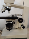
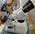
Eventually I had some time to finish my small project for an adaptor 3D printed to adapt my Fuji Mirrorless camera to the Leica microscope.
Some summary that may helps other beginners like me, with no competence on mechanical design and 3D Printing. Please note these are advices from a begineer to begineers... I Am sure there are people much more competent here then me that can help to get better results.. but a begineer guide can sometimes helps
Target: Connect the camera (without lens) to Leica microscope (with eyepiece mounted). I know there are other solutions to be explored but I have preferred the solution without lens because the camera is lighter and since i have only a binocular microscope I did not want to overload the adaptor and the microscope tube with too much weight.
1) I bought an adaptor Fuji bajonet to M42x1:
https://www.amazon.it/gp/product/B00L7E ... UTF8&psc=1
2) I tested the optimal distance of the camera (without lens) from the eyepiece. To make this test I have mounted the camera on the tripod to get stability. Basically the microscope will work as a "lens" for the camera and in my case, I found that the image is in focus and with the right dimension when the camera opening (where you mount the bayonet) is at 32 mm from the eyepiece. (please check my previous message here)
Please note that you need to re-focus the microscope when you pass from the eye view to the view through the camera. ( i think experts say it is not "parafocal" )
3) I have selected a CAD (Autocad Fusion is free of charge and pretty intuitive... with a couple of youtube trainings you can learn the basics). I have designed the adaptor with M42x1 thread from one side and a a tube from the other side, just few mm larger then the microscope tube. Please check drawing here.
4) I could get the part done either with CNC lathe or by 3d printing. I have decided 3d printing for 2 reasons: it is cheaper (30 Euro) and.... I could not find somebody ready to produce one single adaptor with a Lathe
5) A large concern was if I could 3d print a M42 thread.. and the answer is yes and it is pretty solid ! Just follow the below indications to increase the clearance between the 3d printed thread and the metallic thread from the adaptor I bought in amazon:
https://www.youtube.com/watch?v=1nhcKn7Kt8w
Last words: it was really fun to learn so many new things in this project... !
Some summary that may helps other beginners like me, with no competence on mechanical design and 3D Printing. Please note these are advices from a begineer to begineers... I Am sure there are people much more competent here then me that can help to get better results.. but a begineer guide can sometimes helps
Target: Connect the camera (without lens) to Leica microscope (with eyepiece mounted). I know there are other solutions to be explored but I have preferred the solution without lens because the camera is lighter and since i have only a binocular microscope I did not want to overload the adaptor and the microscope tube with too much weight.
1) I bought an adaptor Fuji bajonet to M42x1:
https://www.amazon.it/gp/product/B00L7E ... UTF8&psc=1
2) I tested the optimal distance of the camera (without lens) from the eyepiece. To make this test I have mounted the camera on the tripod to get stability. Basically the microscope will work as a "lens" for the camera and in my case, I found that the image is in focus and with the right dimension when the camera opening (where you mount the bayonet) is at 32 mm from the eyepiece. (please check my previous message here)
Please note that you need to re-focus the microscope when you pass from the eye view to the view through the camera. ( i think experts say it is not "parafocal"
3) I have selected a CAD (Autocad Fusion is free of charge and pretty intuitive... with a couple of youtube trainings you can learn the basics). I have designed the adaptor with M42x1 thread from one side and a a tube from the other side, just few mm larger then the microscope tube. Please check drawing here.
4) I could get the part done either with CNC lathe or by 3d printing. I have decided 3d printing for 2 reasons: it is cheaper (30 Euro) and.... I could not find somebody ready to produce one single adaptor with a Lathe
5) A large concern was if I could 3d print a M42 thread.. and the answer is yes and it is pretty solid ! Just follow the below indications to increase the clearance between the 3d printed thread and the metallic thread from the adaptor I bought in amazon:
https://www.youtube.com/watch?v=1nhcKn7Kt8w
Last words: it was really fun to learn so many new things in this project... !
- Attachments
-
- Foto adattatore small.jpg (74.38 KiB) Viewed 10343 times
-
- Foto adattatore Leica small.jpg (65.68 KiB) Viewed 10343 times
-
- sezione adattore M42x1.jpg (75.15 KiB) Viewed 10343 times
-
- adattatore M42x1.jpg (16.9 KiB) Viewed 10343 times
Last edited by Marco68 on Wed Jul 01, 2020 12:00 pm, edited 1 time in total.
Marco from Italy/Torino
Leica DMLS microscope with 4x, 10x, 40x, 100x
Leica DMLS microscope with 4x, 10x, 40x, 100x
Re: Help needed to design adaptor for Mirrorless camera
Thanks Michael, All for the help given here in this forum !!
Marco from Italy/Torino
Leica DMLS microscope with 4x, 10x, 40x, 100x
Leica DMLS microscope with 4x, 10x, 40x, 100x
Re: Help needed to design adaptor for Mirrorless camera
My next step to improve the adaptor....is there a way to make it parafocal ?
Marco from Italy/Torino
Leica DMLS microscope with 4x, 10x, 40x, 100x
Leica DMLS microscope with 4x, 10x, 40x, 100x
Re: Help needed to design adaptor for Mirrorless camera
You could:
[EDIT: changed shrinks to expands]
- bring the camera closer to the microscope, so that the eyepiece tube intermediate image plane is at the camera's image sensor, and get vignetting
- introduce a relay lens between the 'scope and camera that expands the image to just cover the APS-C sensor
- use a different, short flange focal distance camera that has a smaller, 1- or 4/3-inch sensor (for a typical image), for example, a Nikon 1 or a micro four thirds system camera.
[EDIT: changed shrinks to expands]
Last edited by jfiresto on Sun Jul 05, 2020 10:00 am, edited 1 time in total.
-John
-
viktor j nilsson
- Posts: 762
- Joined: Thu Aug 23, 2018 10:12 pm
- Location: Lund, Sweden
Re: Help needed to design adaptor for Mirrorless camera
Parfocality really is the most reliable way to tell if your sensor is located exactly at the intermediate image. I would setup your camera on a tripod and adjust its position until you found the exact position where everything is parfocal. Then make an adapter that will put your camera there. It might be that you won't be able to place your sensor where it needs to be.
Re: Help needed to design adaptor for Mirrorless camera
Yes, the crux is getting close enough for parfocal, direct projection. The camera flange may need to sit almost 30mm into the original eyepiece tube. Perhaps you could decapitate a tube and make two quick-change adapters: a short one for the camera and a longer one when you want to use the eyepiece.
-John
Re: Help needed to design adaptor for Mirrorless camera
Hi All,
can anybody help me to understand why I get the pictures out of focus with my camera Fuji Mirrorless and the above descriped adaptor, even if on the display of the Mirrorless camera they looks pretty in focus ? I get the same indipendently from the shutter speed and ISO settings .
Thanks
M.
can anybody help me to understand why I get the pictures out of focus with my camera Fuji Mirrorless and the above descriped adaptor, even if on the display of the Mirrorless camera they looks pretty in focus ? I get the same indipendently from the shutter speed and ISO settings .
Thanks
M.
- Attachments
-
- Fuji Display 2.jpg (158.45 KiB) Viewed 9092 times
-
- DSCF2915.JPG (74.96 KiB) Viewed 9092 times
Marco from Italy/Torino
Leica DMLS microscope with 4x, 10x, 40x, 100x
Leica DMLS microscope with 4x, 10x, 40x, 100x
Re: Help needed to design adaptor for Mirrorless camera
Made an adapter many years ..goes in like an eyepiece...used a t-ring adapter and machined the insert part
Re: Help needed to design adaptor for Mirrorless camera
Thanks. I do not think vibration is the issue. It is a mirrorless camera that should generate minimum vibration
Marco from Italy/Torino
Leica DMLS microscope with 4x, 10x, 40x, 100x
Leica DMLS microscope with 4x, 10x, 40x, 100x
-
viktor j nilsson
- Posts: 762
- Joined: Thu Aug 23, 2018 10:12 pm
- Location: Lund, Sweden
Re: Help needed to design adaptor for Mirrorless camera
Are you using electronic shutter? My quick search on the XE2 suggest that it can operate both in mechanical shutter and electronic shutter mode. In the mechanical shutter mode the shutter has to close, open, close, open to take a picture, which can absolutely cause the vibration problems in your picture.
It does look like vibration problems, so I don't think you should brush that off so easily.
It does look like vibration problems, so I don't think you should brush that off so easily.
Re: Help needed to design adaptor for Mirrorless camera
When I searched that camera model there were some mentions of firmware version, like an upgrade might be necessary to add the electronic shutter modes.
Re: Help needed to design adaptor for Mirrorless camera
Hi Hans, Viktor
Thanks ! I have read the same info right now and I will definitely upgrade the firmware to get e-Shutter. Let's see if i can get sharper images!
Thanks ! I have read the same info right now and I will definitely upgrade the firmware to get e-Shutter. Let's see if i can get sharper images!
Marco from Italy/Torino
Leica DMLS microscope with 4x, 10x, 40x, 100x
Leica DMLS microscope with 4x, 10x, 40x, 100x
Re: Help needed to design adaptor for Mirrorless camera
Hi All,
I have upgraded the firmware of my Fuji X-E2 to Ver. 4 and I have set the shutter to electronic mode.
Final result is much better ! Still not as sharp as I would like to get, but I think this is an acceptable result.
Any advice to further improve the image sharpness (of course a part from image post processing) ?
Thanks !!
- Attachments
-
- cianobatterio_oscillatoria.jpg (89.38 KiB) Viewed 8808 times
Marco from Italy/Torino
Leica DMLS microscope with 4x, 10x, 40x, 100x
Leica DMLS microscope with 4x, 10x, 40x, 100x
Re: Help needed to design adaptor for Mirrorless camera
Use a remote shutter release to avoid jarring the microscope and camera, or the self-timer to wait for both to settle after you press the shutter button?
-John