Post articles here that do not fit into other categories. I may add more categories to accommodate these posts.
-
MichaelG.
- Posts: 4045
- Joined: Mon Apr 10, 2017 8:24 am
- Location: North Wales
#31
Post
by MichaelG. » Thu Jul 11, 2019 9:05 pm
MichaelG. wrote:Hobbyst46 wrote:BTW: what is a "friction drive focus" ?
If you look at the photo posted earlier ... there is a vertical [probably chromium plated] rod: The focus wheel is spring-loaded against this, to provide traction ... No gears as such.
It's a simple but effective drive, also used on many photographic enlargers, but does not provide fine adjustment.
That is my understanding ... I will photograph some details when I receive the microscope.
MichaelG.
Sincere apologies ... I was wrong

The vertical rod is just for alignment
There is in fact a [rather coarse] rack & pinion drive for focus

- Meopta_focus.jpg (200.05 KiB) Viewed 11022 times
MichaelG.
Too many 'projects'
-
Hobbyst46
- Posts: 4292
- Joined: Mon Aug 21, 2017 9:02 pm
#32
Post
by Hobbyst46 » Thu Jul 11, 2019 9:26 pm
MichaelG. wrote:MichaelG. wrote:Hobbyst46 wrote:BTW: what is a "friction drive focus" ?
If you look at the photo posted earlier ... there is a vertical [probably chromium plated] rod: The focus wheel is spring-loaded against this, to provide traction ... No gears as such.
It's a simple but effective drive, also used on many photographic enlargers, but does not provide fine adjustment.
MichaelG.
The vertical rod is just for alignment
There is in fact a [rather coarse] rack & pinion drive for focus
MichaelG.
That is very good. A coarse rack&pinion means fairly reproducible focusing that is not so sensitive to dust and mud (field jobs).
I now recollect, that the vertical drive on my small low-end ROWI enlarger was indeed friction ! Better models had handles and precise mechanical focus drives, maybe in addition to friction.
-
MichaelG.
- Posts: 4045
- Joined: Mon Apr 10, 2017 8:24 am
- Location: North Wales
#33
Post
by MichaelG. » Thu Jul 11, 2019 9:59 pm
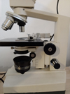
Here are a couple more details of the Meopta
First, one the clips that [supposedly] retain the can

- Meopta_latch_open.jpg (171.03 KiB) Viewed 11017 times
This one will need the 'hook' re-shaping a little.
Now, the head of the microscope

- 'scope is lying flat, so 20x objective is not extended
- Meopta_loose_head.jpg (214.32 KiB) Viewed 11017 times
The two screws were very loose.
Some tinkering and tidying required, but it's certainly lightweight and compact.
MichaelG.
Too many 'projects'
-
75RR
- Posts: 8207
- Joined: Sun Oct 12, 2014 2:34 am
- Location: Estepona, Spain
#34
Post
by 75RR » Fri Jul 12, 2019 7:50 am
Nice to see the details ... looks to be in good condition though the clasps (assuming the other one is in similar condition),
could do with sitting in white vinegar for a couple of hours or so.
Zeiss Standard WL (somewhat fashion challenged) & Wild M8
Olympus E-P2 (Micro Four Thirds Camera)
-
Hobbyst46
- Posts: 4292
- Joined: Mon Aug 21, 2017 9:02 pm
#35
Post
by Hobbyst46 » Fri Jul 12, 2019 8:02 am
75RR wrote:... could do with sitting in white vinegar for a couple of hours or so.
Or citric acid solution (the powder is found among the spices). A most efficient rust remover is dilute phosphoric acid (say, 10% in water). Some commercial pink-tinted liquid rust removers contain this acid.
-
MichaelG.
- Posts: 4045
- Joined: Mon Apr 10, 2017 8:24 am
- Location: North Wales
#36
Post
by MichaelG. » Fri Jul 12, 2019 8:30 am
75RR wrote:Nice to see the details ... looks to be in good condition [ ... ]
I get the impression that it has been very little used
My guess is that
1. the two screws came loose fairly early in its life [*] and
2. the ineffective clip was troublesome
so it was put on a shelf in the garage, until ebay found it a new home.
MichaelG.
.
[*] the objective turret action is quite firm, and rotation forces would be transferred to the head fixing; which is, frankly, not well-engineered.
Too many 'projects'
-
75RR
- Posts: 8207
- Joined: Sun Oct 12, 2014 2:34 am
- Location: Estepona, Spain
#37
Post
by 75RR » Fri Jul 12, 2019 11:49 am
[*] the objective turret action is quite firm, and rotation forces would be transferred to the head fixing; which is, frankly, not well-engineered.
I think the problem is more the build quality (read tolerances) rather than the design. With a tighter fit there would be no force applied to the screws that hold the head on.
Perhaps some shims would help?
-
Attachments
-

- shims.jpg (57.24 KiB) Viewed 10976 times
Zeiss Standard WL (somewhat fashion challenged) & Wild M8
Olympus E-P2 (Micro Four Thirds Camera)
-
MichaelG.
- Posts: 4045
- Joined: Mon Apr 10, 2017 8:24 am
- Location: North Wales
#38
Post
by MichaelG. » Fri Jul 12, 2019 12:26 pm
75RR wrote:[*] the objective turret action is quite firm, and rotation forces would be transferred to the head fixing; which is, frankly, not well-engineered.
I think the problem is more the build quality (read tolerances) rather than the design. With a tighter fit there would be no force applied to the screws that hold the head on.
Perhaps some shims would help?
Having detached the head from the stand; it is evident that
both design and execution are poor.
The gaps that you point to are only
so obvious because the screws were loose !
I will take more photos [probably tomorrow] to show the 'mating' arrangement.
... Current thinking is to introduce shims/gaskets of aluminium baking foil.
Thanks for your thoughts
MichaelG.
Too many 'projects'
-
Roldorf
- Posts: 574
- Joined: Tue Apr 23, 2019 6:58 pm
- Location: Northern Germany
#39
Post
by Roldorf » Fri Jul 12, 2019 3:31 pm
Aluminium will 'pick up' you need brass shims.
Location: Northern Germany
Unknown Brand: Optika SFX 91: Bresser Science Infinity: Canon 4000d
-
MichaelG.
- Posts: 4045
- Joined: Mon Apr 10, 2017 8:24 am
- Location: North Wales
#40
Post
by MichaelG. » Fri Jul 12, 2019 3:53 pm
Roldorf wrote:Aluminium will 'pick up' you need brass shims.
The Aluminium is proposed as a thin conformable gasket between two painted surfaces ... and is intended to remain static.
MichaelG.
Too many 'projects'
-
MichaelG.
- Posts: 4045
- Joined: Mon Apr 10, 2017 8:24 am
- Location: North Wales
#41
Post
by MichaelG. » Mon Jul 15, 2019 8:17 pm
With apologies for the delay, here are a couple more details
First the location and fixing arrangement for the head:

- No positive location ...
- Meopta_head-fixing.jpg (182.38 KiB) Viewed 10900 times
The slotted grub-screw is a loose fit in the hole; so there is no positive location and the two fixing screws are doing most of the work.
Now some good news: Slotted holes allow for adjustment of the catches

- Slotted holes in the can
- Meopta_can-slots.jpg (140.15 KiB) Viewed 10900 times
Note that both photos show items conveniently laid on the table
MichaelG.
Too many 'projects'
-
Hobbyst46
- Posts: 4292
- Joined: Mon Aug 21, 2017 9:02 pm
#42
Post
by Hobbyst46 » Mon Jul 15, 2019 8:34 pm
I am not clear about the slotted holes - where they are located.
Primitive solution no 1. Replace the slotted grub-screw with a round-head bolt of the same thread - I mean, its head should be a small cylinder and snugly fit into the opposing hole. This will be possible IF and only IF the two existing black bolts have lateral positioning freedom.
Primitive and laborious solution no 2. Make an H-cross section bridge, a single piece, to go around the slotted grub-screw, and externally clamp both the black and beige parts. The horizontal bar of the "H" should be thin enough to fit into the narrow space between the black and beige parts, and the H must be made of a strong substance (steel). A drilled hole in the horizontal bar will let the grub screw head pass through.
Probably too difficult to make though.
Last edited by
Hobbyst46 on Mon Jul 15, 2019 8:43 pm, edited 3 times in total.
-
Hobbyst46
- Posts: 4292
- Joined: Mon Aug 21, 2017 9:02 pm
#43
Post
by Hobbyst46 » Mon Jul 15, 2019 8:40 pm
If you still consider simple shims, and can tell the approximate size, I can check if some of my thin steel shims (left overs) might fit, and PM you.
-
MichaelG.
- Posts: 4045
- Joined: Mon Apr 10, 2017 8:24 am
- Location: North Wales
#44
Post
by MichaelG. » Mon Jul 15, 2019 8:45 pm
Hobbyst46 wrote:I am not clear about the slotted holes - where they are located.
Revealed when the latch/clip was removed ...
[
Sorry! ... I probably should have rotated the image 90° anticlockwise ]

- Photo re-orientated !
- Meopta_can-slots.jpg (118.09 KiB) Viewed 10889 times

- Meopta_latch_open.jpg (171.03 KiB) Viewed 10892 times
MichaelG.
.
P.S. ... I'm happy that I can improve the head fixing ... but many thanks for your thoughts.
Last edited by
MichaelG. on Mon Jul 15, 2019 8:55 pm, edited 1 time in total.
Too many 'projects'
-
MicroBob
- Posts: 3154
- Joined: Sun Dec 25, 2016 9:11 am
- Location: Northern Germany
#45
Post
by MicroBob » Mon Jul 15, 2019 8:52 pm
MichaelG. wrote:
The slotted grub-screw is a loose fit in the hole; so there is no positive location and the two fixing screws are doing most of the work.
MichaelG.
Hi Michael,
it has been some time since I have dismantled my Meopta but I don't think the grub screw is intended to do the allocation. The hole in the beige part will be only there to make room for it.
The two screws can easily handle the forces and the paint, stil a bit soft at production time, equalizes the uneven mating surfaces.

The gaps are just cosmetic problems, not more. As long as everything is in line and right angle this will work just fine. An M4 screw can withstand quite some force before it elongates unduly.
Bob
-
MichaelG.
- Posts: 4045
- Joined: Mon Apr 10, 2017 8:24 am
- Location: North Wales
#46
Post
by MichaelG. » Mon Jul 15, 2019 9:07 pm
MicroBob wrote:MichaelG. wrote:
The slotted grub-screw is a loose fit in the hole; so there is no positive location and the two fixing screws are doing most of the work.
MichaelG.
Hi Michael,
it has been some time since I have dismantled my Meopta but I don't think the grub screw is intended to do the allocation. The hole in the beige part will be only there to make room for it.
The two screws can easily handle the forces and the paint, stil a bit soft at production time, equalizes the uneven mating surfaces.
The gaps are just cosmetic problems, not more. As long as everything is in line and right angle this will work just fine. An M4 screw can withstand quite some force before it elongates unduly.
Bob
Thanks for the info. Bob ...
But; as I said previously the Black bit was
rattling loose when I received the instrument: The two screws were at least one turn slack, and were easily removed with a hex-shank screwdiver bit held twixt thumb and finger !!
MichaelG.
Too many 'projects'
-
Hobbyst46
- Posts: 4292
- Joined: Mon Aug 21, 2017 9:02 pm
#47
Post
by Hobbyst46 » Mon Jul 15, 2019 9:12 pm
Spring washers for the two bolts, and the red loctite stuff for the loose slotted grub-screw ?
-
MichaelG.
- Posts: 4045
- Joined: Mon Apr 10, 2017 8:24 am
- Location: North Wales
#48
Post
by MichaelG. » Tue Jul 16, 2019 8:26 am
Hobbyst46 wrote:Spring washers for the two bolts, and the red loctite stuff for the loose slotted grub-screw ?
Sorry Doron ... I appear to have misled you again
When I wrote:
The slotted grub-screw is a loose fit in the hole ...
I should probably have written:
The slotted grub-screw is a loose fit in the recess in the beige component; so it does not provide the positive location that a dowel-pin might ...
Note: The screw is adequately tight in its thread.
MichaelG.
Too many 'projects'
-
FairFrank
- Posts: 2
- Joined: Mon May 31, 2021 4:27 am
#49
Post
by FairFrank » Mon May 31, 2021 4:41 am
Hi and sorry for the up pals. I've found this thread via google because I'm curious about choosing my first portable microscope. What do you think about Carsons and Levenhuk's scopes? What's the difference?


