How does objective strain show up in DIC images?
How does objective strain show up in DIC images?
After the recent discussion in Louise's thread I am curious what effects exactly objective strain birefringence typically has on the DIC image. There are plenty of references stating the importance of using strain-free objectives but I haven't found any examples images from strained objectives, either the actual image of the specimen or what the BFP looks like. Anyone seen examples, or can describe from experience?
-
LouiseScot
- Posts: 1167
- Joined: Tue Jul 07, 2020 1:51 pm
- Location: Scotland
Re: How does objective strain show up in DIC images?
I was wondering about that too! But I figured it was unlikely to be the source of big problems for hobbyists. Of course, I need to get the DIY DIC working first in order to see for myself! However, if it comes to it, I have a Nikon CFI 60 20x which is marked ok for DIC. Interested to hear from some Nomarski DIC users.hans wrote: ↑Fri Jul 02, 2021 8:26 pmAfter the recent discussion in Louise's thread I am curious what effects exactly objective strain birefringence typically has on the DIC image. There are plenty of references stating the importance of using strain-free objectives but I haven't found any examples images from strained objectives, either the actual image of the specimen or what the BFP looks like. Anyone seen examples, or can describe from experience?
Louise
A Nikon CF plan 20x; A Swift 380T; A DIY infinity corrected focus rail system with a 40x/0.65 Olympus Plan, a 10x/0.30 Amscope Plan Fluor, and a 20x/0.75 Nikon Plan Apo
-
viktor j nilsson
- Posts: 761
- Joined: Thu Aug 23, 2018 10:12 pm
- Location: Lund, Sweden
Re: How does objective strain show up in DIC images?
The easiest way to check for strain is too look at the back focal plane with crossed polarizers. It should look like (a):
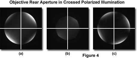
But if an objective has strain the cross won't be black and irregular. When I was playing with my DIY DIC setup I remember seeing one objective that seemed to be stained, but I can't really remember how it affected the results. There were too many uncontrolled variables there anyway. With my Vanox DIC, the analyzer and objective prism are attached to each other, so I never see the polarization cross at the back focal plane. I might put on my Pol intermediate piece someday and check my objectives...
Anyway, if objectives are weakly or moderately strained, I expect that the effect on DIC will be that the background is grey rather than black at maximum extinction. I think they need to be quite badly strained to really mess things up.
Re: How does objective strain show up in DIC images?
Interesting, I had noticed the cross pattern before when using polarized light and read a little about conoscopy but still don't understand how exactly the cross is formed, much less how the rotation of the cross shown in (c) would be expected to interact with the DIC fringe pattern.
-
viktor j nilsson
- Posts: 761
- Joined: Thu Aug 23, 2018 10:12 pm
- Location: Lund, Sweden
Re: How does objective strain show up in DIC images?
The view in (c) is just an effect of not having the crossed polarizers set in a purely North-South orientation. I took it from this page, which is only about Pol microscopy: https://micro.magnet.fsu.edu/primer/tec ... nment.htmlhans wrote: ↑Sat Jul 03, 2021 5:04 amInteresting, I had noticed the cross pattern before when using polarized light and read a little about conoscopy but still don't understand how exactly the cross is formed, much less how the rotation of the cross shown in (c) would be expected to interact with the DIC fringe pattern.
If you would see a rotated cross at the BFP, and your nomarski prisms go in at a 45° angle, then that would not work well. DIC is quite sensitive to the orientation of the prisms and analyzer. A few ° off is enough to really reduce the effect.
The most detailed step-by-step illustration of how the BFP looks like when setting up DIC that I know of is this:
https://www.olympus-lifescience.com/ja/ ... iguration/
It shows very well that the polarization cross is still evident at the BFP with DIC at full extinction, but more magnified. In fact, in my experience, that is a very good sign of a truly perfectly aligned DIC setup. When you translate the prism and approach full extinction, the BFP gets "invaded" by darkness from four quadrants simultaneously. It's pretty cool actually, the four dark quadrants almost "rotates" into view at the BFP. I've only seen that with the plan achromat objectives for which my DIC setup was originally designed. With mismatched PlanApo's, "maximum extinction" is instead seen as a relatively broad dark band traveling across the BFP. The DIC effect is still pretty good at the image plane, so it's not totally critical to achieve that level of perfection. But it's a very good sign that you have achieved perfect alignment of everything when you see it.
Re: How does objective strain show up in DIC images?
I see, was thinking (c) was showing a typical symptom of strain in the objective.
Yeah nice illustrations, and they even have the microplicae (?) I was wondering about showing up clearly in figure 10(a) demonstrating correct DIC configuration.viktor j nilsson wrote: ↑Sat Jul 03, 2021 6:30 amThe most detailed step-by-step illustration of how the BFP looks like when setting up DIC that I know of is this:
https://www.olympus-lifescience.com/ja/ ... iguration/
Is this a symptom of a small magnification mismatch between the prisms? For example say one prism shows retardance varying -500 to 500 nm across the pupil and the other a slightly broader fringe pattern 450 to -450 nm. Then together the residual goes -50 to 50 nm and the dark band seen crossing the pupil is the center of a very wide fringe pattern?viktor j nilsson wrote: ↑Sat Jul 03, 2021 6:30 amWith mismatched PlanApo's, "maximum extinction" is instead seen as a relatively broad dark band traveling across the BFP.
-
viktor j nilsson
- Posts: 761
- Joined: Thu Aug 23, 2018 10:12 pm
- Location: Lund, Sweden
Re: How does objective strain show up in DIC images?
Interesting thought. I have always assumed that it is because of a mismatch between the location of the objective back focal plane and the location of the interference fringe(s). I've just assumed that two objectives from the same maker and era (like the Olympus short barrel 40x plan achromat and 40x planapo) are more likely to show meaningful differences in the location of their BFP than in focal length.hans wrote: Is this a symptom of a small magnification mismatch between the prisms? For example say one prism shows retardance varying -500 to 500 nm across the pupil and the other a slightly broader fringe pattern 450 to -450 nm. Then together the residual goes -50 to 50 nm and the dark band seen crossing the pupil is the center of a very wide fringe pattern?
Re: How does objective strain show up in DIC images?
Yeah, seems likely.viktor j nilsson wrote: ↑Sat Jul 03, 2021 5:56 pmI've just assumed that two objectives from the same maker and era (like the Olympus short barrel 40x plan achromat and 40x planapo) are more likely to show meaningful differences in the location of their BFP than in focal length.
Moving just one prism would generally cause both magnification change and defocusing of the fringe patterns relative to one another, I think? Maybe it does not make sense to try to separate the effects, but could imagine a different choice of coordinates to represent small errors in the prism positions:
- Pure magnification change -- prisms moved in the same direction (but generally different distances) maintaining conjugacy between them. (Space between condenser and objective is no longer focused at infinity.)
- Pure defocus -- prisms moved in opposite directions (but again generally different distances) while keep magnification constant.
Re: How does objective strain show up in DIC images?
Oops, just noticed I confusingly quoted the wrong part of your post, edited now.