Darkfield diagnostic test slide

Here you can discuss different microscopic techniques and illumination methods, such as Brightfield, Darkfield, Phase Contrast, DIC, Oblique illumination, etc.
Post Reply
Message
Author
Chas
Posts: 432
Joined: Tue Jan 19, 2021 3:11 pm

Darkfield diagnostic test slide

#1 Post by Chas » Mon Nov 27, 2023 9:28 am

Messing about with various darkfield condensers with some success and some failures, I wanted to see what was going on with the failures.

I used a white 'water-based liquid chalk' marker pen, but the particles were a bit too dense, dipping the tip of the pen in a few drops of water 3 times seemed to make things better.
The nearest slide seems to me to be about the right dilution:
DF condenser slide liquid chalk pen.jpg
DF condenser slide liquid chalk pen.jpg (98.05 KiB) Viewed 69462 times
The coverslip was put on with SuperGlue ... a drop on the coverslip, turn it over (not too slowly!) and lower it down. The chalk seems accelerate the glue ; in two minutes the slide can be moved without it glueing to your fingers :-)

Phill Brown
Posts: 608
Joined: Mon May 24, 2021 1:19 pm
Location: Devon UK.

Re: Darkfield diagnostic test slide

#2 Post by Phill Brown » Mon Nov 27, 2023 9:52 am

Interested to see how you get on.
Canada balsam and xylene here.
A little bit goes a long way,spill a few drops for a whole new experience in clean up.

Chas
Posts: 432
Joined: Tue Jan 19, 2021 3:11 pm

Re: Darkfield diagnostic test slide

#3 Post by Chas » Mon Nov 27, 2023 3:13 pm

Superglue is not a good mount! ..but it was deadly quick ; the refractive index seems quite different where it starts to set... the slides show a curious ripple effect.
The 'screen' does help if things arent going as they should ..I had a slightly twisted mount with a CTS , one DF patched abbe condenser that couldnt get quite close enough to the slide, a couple of cases where I hadnt got the light aligned perfectly and some condensers seemed to show two quite different DF foci (!)

To give an idea of what it looks like: Here is a pic of an image of a 2 inch square diffuse light source on the diluted chalk mark with a 4x objective:
Watson Zonal DG oil on chalk marker 4x direct proj.jpg
Watson Zonal DG oil on chalk marker 4x direct proj.jpg (124.29 KiB) Viewed 69413 times


And here is one edge of the diluted chalk mark with a 50x objective:
Watson zonal oil DF with watson flourite phase direct proj 002 800.jpg
Watson zonal oil DF with watson flourite phase direct proj 002 800.jpg (72.02 KiB) Viewed 69413 times

Phill Brown
Posts: 608
Joined: Mon May 24, 2021 1:19 pm
Location: Devon UK.

Re: Darkfield diagnostic test slide

#4 Post by Phill Brown » Mon Nov 27, 2023 7:05 pm

Is that the X50 .95 Watson oil?

Chas
Posts: 432
Joined: Tue Jan 19, 2021 3:11 pm

Re: Darkfield diagnostic test slide

#5 Post by Chas » Mon Nov 27, 2023 7:53 pm

Yes, the long modern sort. I tried it with an older 3.75mm 0.95 Beck too ...both the the same.
I have just scuttled off and got my micrometer; the slide thickness is ~1.1mm.

Sure Squintsalot
Posts: 399
Joined: Mon May 16, 2022 3:44 pm

Re: Darkfield diagnostic test slide

#6 Post by Sure Squintsalot » Mon Nov 27, 2023 10:17 pm

Your "diagnostic test slide" shows promise, I think. However, to be truly diagnostic you'd probably want to know the particle size and use a mountant as close to a RI of 1.5 as possible.

Maybe we could, as a community, find "inks" with a particle size in the 300nm range; diagnosing super-resolution dark field set-ups would be enormously cool and useful.

Phill Brown
Posts: 608
Joined: Mon May 24, 2021 1:19 pm
Location: Devon UK.

Re: Darkfield diagnostic test slide

#7 Post by Phill Brown » Tue Nov 28, 2023 8:18 am

The Watson zonal DF oil condenser has a small refractive indent in the centre of the top lens.
It can be seen in the 4x image as a ring around the central square of illumination.
It's oil filled,not user serviceable.
Realistically the na is still limited to .95.
Considering it's 1950's RMS it's still very effective for resolution.
The brochure says it's not suitable for the microsystem 70 but I haven't found why that was suggested.
Can be challenging to find the first one.
Can't say it's more rewarding than some DIY alternatives with an abbe.

MichaelG.
Posts: 4027
Joined: Mon Apr 10, 2017 8:24 am
Location: North Wales

Re: Darkfield diagnostic test slide

#8 Post by MichaelG. » Tue Nov 28, 2023 9:51 am

You are probably aware of this resource, Phill … but I will put it here for general reference:
https://cnum.cnam.fr/pgi/fpage.php?M997 ... 00/119/0/0

[ hopefully that links to Page 31 ]

MichaelG.
Too many 'projects'

apochronaut
Posts: 6327
Joined: Fri May 15, 2015 12:15 am

Re: Darkfield diagnostic test slide

#9 Post by apochronaut » Tue Nov 28, 2023 10:41 am

Resolution test slides have value only if the grid or particle size is known. Up until recently , diatoms have served that purpose and across most illumination techniques.
Once ca shows up in the image, it throws a question mark on the system because it masks resolution. One of the principle values of DF is that it is potentially a ca free imaging system, so that it can show inclusions and embedded details within a fairly homogeneous matrix well. Once ca becomes evident, those details lose definition, so resolution becomes irrelevant. It becomes kind of like fluorescence in some ways, you can see that the structure or particle is there but you cannot really determine anything about it.

Hobbyst46
Posts: 4288
Joined: Mon Aug 21, 2017 9:02 pm

Re: Darkfield diagnostic test slide

#10 Post by Hobbyst46 » Tue Nov 28, 2023 12:45 pm

Perhaps a more or less uniform layer of small opaque particles of a defined diameter can serve for that purpose. Polystyrene spheres and other polymer particles are available from lab suppliers as suspensions that can be diluted with water as needed. A dried drop on the coverslip will make the test slide. Home-available alternatives - maybe diluted milk (a suspension of fat globules). Another, less elegant idea - a coverslip that has been very lightly exposed to cigarette smoke, so is coated with soot particles. Soot particles are visible when they float in air (Tyndall effect) so, I think, can serve on a slide as well. But never tried any of those ideas.

Phill Brown
Posts: 608
Joined: Mon May 24, 2021 1:19 pm
Location: Devon UK.

Re: Darkfield diagnostic test slide

#11 Post by Phill Brown » Tue Nov 28, 2023 6:58 pm

MichaelG. wrote:
Tue Nov 28, 2023 9:51 am
You are probably aware of this resource, Phill … but I will put it here for general reference:
https://cnum.cnam.fr/pgi/fpage.php?M997 ... 00/119/0/0

[ hopefully that links to Page 31 ]

MichaelG.
Thanks.
That's an older version?
Later is code 155/4 1.2mm.
Funnel stop for x100/1.30 is code 786.
Funnel stop for x90/1.30 FL is code 781.
Just so you know the parts are out there.
I have a x90/1.37 short barrel type.
The stops are a screw in type.

Chas
Posts: 432
Joined: Tue Jan 19, 2021 3:11 pm

Re: Darkfield diagnostic test slide

#12 Post by Chas » Tue Nov 28, 2023 9:14 pm

The Watson zonal DF oil condenser has a small refractive indent in the centre of the top lens.
It can be seen in the 4x image as a ring around the central square of illumination.
It's oil filled,not user serviceable.
Realistically the na is still limited to .95.
Considering it's 1950's RMS it's still very effective for resolution.
Interesting; I have a Watson threaded one with a ~3/4" diameter glass on the top; there is no sign of oil inside it.
Looks like this:
Zonal DG condenser Watson thread fit 800.jpg
Zonal DG condenser Watson thread fit 800.jpg (120.68 KiB) Viewed 69204 times
Except that it has a black circle on the top much like I imagine 'spot lenses' to have.
I reckon that the thing in the middle is an engraved centering ring.
Quite envious of a Watson threaded RMS adapter ! :-)

Yup its a 'diagnostic test slide' more for mirror twizzling, centering, focussing, that kind of thing .. but I am pretty sure that one could still pick a pair of just-seperable fine grains and measure the spacing.
Hobbyst46... thanks, I have just drawn the marks on the underside of the coverslip ! ( and mounted this onto the slide with 'Bondic' UV cure glue ... this stuff still has a refractive wave in it, but now it doesn't get in front of the objective's view :-) )

A Diatom??? What a crazy idea ..that would be like volunteering to fall into a black/rabbit hole (in the UK) unfortunately they are a bit like cigarettes, I try not to.

Phill Brown
Posts: 608
Joined: Mon May 24, 2021 1:19 pm
Location: Devon UK.

Re: Darkfield diagnostic test slide

#13 Post by Phill Brown » Tue Nov 28, 2023 9:21 pm

That's the one.
I can assure you it is oil filled.
I have RMS adaptors and all sorts.
Got 3 of the DG zonal.
Also a Watson universal condenser to RMS objective adapter.
I'm in the UK, Watson did diatom test slides.
Only have one of those.
I have the end of line stock of Canada balsam dropper bottles.
There's no going back from there.

apochronaut
Posts: 6327
Joined: Fri May 15, 2015 12:15 am

Re: Darkfield diagnostic test slide

#14 Post by apochronaut » Wed Nov 29, 2023 2:00 am

Chas wrote:
Tue Nov 28, 2023 9:14 pm


A Diatom??? What a crazy idea ..that would be like volunteering to fall into a black/rabbit hole (in the UK) unfortunately they are a bit like cigarettes, I try not to.
standard issue resolution test objects going on 150 years now. don't try reinventing the wheel.

Chas
Posts: 432
Joined: Tue Jan 19, 2021 3:11 pm

Re: Darkfield diagnostic test slide

#15 Post by Chas » Wed Nov 29, 2023 7:41 pm

I am always re-inventing the wheel, every day, in every way :-(
Indeed, I have just come across Simon Gage's '"Modern Dark-field Microscopy" .. it's all in there (nearly) ..a good read..even a nice sounding way to size darkfield patch stops :
https://archive.org/details/jstor-32218 ... 1/mode/2up

Re. the Zonal oil DF condenser ..I managed to take mine apart (fools rush in...)

The silvered head removed from its black tube:
Oil Zonal silver top unscrewed 800.jpg
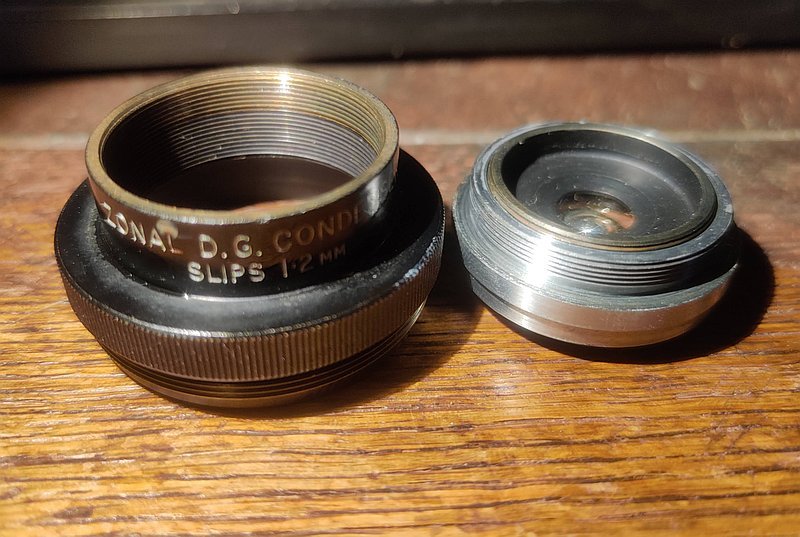
Oil Zonal silver top unscrewed 800.jpg (101.05 KiB) Viewed 69120 times
(I am not sure that I could have done this without MichaelG's PlusGas formula 21 ..I have been using this stuff for about a month and it is very good.....Thanks! )

On the the underside of the optical head there is a stop that unscrews out (mine just unscrewed by pressing a finger on it and turning):
Oil Zonal back plate screwed out.jpg
Oil Zonal back plate screwed out.jpg (110.11 KiB) Viewed 69120 times

Leaving, what looks to me, like a solid block of glass with a pip bored into its front:
Oil Zonal glass element 800.jpg
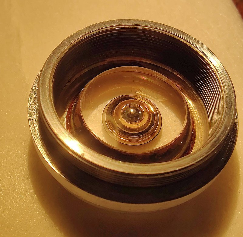
Oil Zonal glass element 800.jpg (126.99 KiB) Viewed 69120 times

My zonal has a round black patch on the front/top of it and this hides the pip ..maybe if your version doesn't have a black circle this is the refractive element you can see (but I cant) ?
The black patch seems to live undeneath a coverglass cemented to the block, mine is delaminating away from it a bit.

What one sees when looking down into the top of the condenser looks to be the top surface of the unscrewable stop.
I guess that oil could weep in and sit between the glass block and the stop (??) presumably these were used in a professional setting and often with a high wattage incandescent illuminator, which could heat them up quite a bit.

MichaelG.
Posts: 4027
Joined: Mon Apr 10, 2017 8:24 am
Location: North Wales

Re: Darkfield diagnostic test slide

#16 Post by MichaelG. » Thu Nov 30, 2023 7:32 am

Thanks for sharing the dissection, Chas … very interesting

MichaelG.
Too many 'projects'

Phill Brown
Posts: 608
Joined: Mon May 24, 2021 1:19 pm
Location: Devon UK.

Re: Darkfield diagnostic test slide

#17 Post by Phill Brown » Thu Nov 30, 2023 7:42 am

It's oil filled.
There is a parabolic mirror also.
I have one that the oil has become discoloured,also has a slight delamination of the patch.
It's not oil that leaked in before we need to ask.
I have another 2 without any issues.

apochronaut
Posts: 6327
Joined: Fri May 15, 2015 12:15 am

Re: Darkfield diagnostic test slide

#18 Post by apochronaut » Thu Nov 30, 2023 11:06 am

I don't have a Watson zonal condenser. I have similar R.M.S. threaded designs from Beck and Cooke. The principle was brilliant. Make a condenser body with an R.M.S. female thread and condensers with male R.M.S. threads to fit it. Where are the BF condensers , though? I only ever see DF condensers.
Well, the reason for the R.M.S. thread is so that a matching objective to the observational one can be used as a condenser. It was a semi popular system primarily pitched at researchers. Having a DF condenser that goes into the body was a bonus. Spencer had a similar set up , offering a 1.3 N.A. achromat aplanat with R.M.S. thread as well but I never have seen a DF one from Spencer. I have used a Beck in the Spencer body though and various matching apochromat objectives as a condenser as well. It was a super system if one could have afforded it, in it's day.

Paraboloid condensers usually have the stop set in the bottom of a glass column and a 360° paraboloid ring mirror silvered onto an inverse parabolic ring polished around the periphery of the glass column near the top. The light bypasses the stop hitting the parabolic mirror , creating a band of light of sufficient diameter to be outside a certain N.A. at a minimum and up to a certain N.A. at a maximum. It then reflects through the upper section of 1.52 n glass to the immersion oil then the slide. There is only one mirror, all else is glass. Paraboloids are said to create a small amount of ca. Paraboloids are quite deep condensers compared to those below.

In spherical and cardioid designs there are two mirrors and only a small glass puck at the top into which all is embedded.The primary mirror is a central convex dome that functions as both the primary mirror and the stop. It reflects the incoming light to an either cardioid or spherical secondary mirror silvered onto the exterior of the puck much in the same way that the paraboloid mirror is silvered onto the upper section of the column in the above design. The light then passes through the top of the condenser, immersion oil, slide continuum at an angle outside the view of the objective.

The Watson zonal appears to be the latter design, yet it is stated to be paraboloid. Is that coming from a catalogue reference or is the primary mirror geometrically different to those above?

Phill Brown
Posts: 608
Joined: Mon May 24, 2021 1:19 pm
Location: Devon UK.

Re: Darkfield diagnostic test slide

#19 Post by Phill Brown » Thu Nov 30, 2023 11:00 pm

IMG-20231130-WA0001.jpg
IMG-20231130-WA0001.jpg (131.4 KiB) Viewed 68915 times
The light is allowed through the aperture through a flat lower lens.
Hits the dome mirror on the back of the patch and is reflected on a mirror around the edge that can be seen through the top.
The top lens has a detent to refract to the sample
The internal oil will be to maximize the refraction at the point in the centre.
The point of light is too small to be of any use below x40/.65.
Some spares in the drawer, they are universal screw fit.

apochronaut
Posts: 6327
Joined: Fri May 15, 2015 12:15 am

Re: Darkfield diagnostic test slide

#20 Post by apochronaut » Fri Dec 01, 2023 3:28 pm

This is a double reflecting condenser with a narrow body. Paraboloids are single reflecting condensers. It looks like and if it achieves .95 N.A. to be either Cardioid, Spherical or Bicentric. It might be a Spot Ring but they require a wider body to accomodate a secondary reflector at a more extreme angle. They are kind of a wide angle Spherical or Bicentric.
Why oil? If the oil introduces refraction then it also introduces ca and also if so, you would see a border between the oil and glass. If there is oil in there and you can't see it, then there is no refraction. The idea , from the secondary reflector upwards is to have a homogeneous state in the optical pathway all the way to the top of the slide. That's why it is oil immersion and of a consistent refractive index from the incoming glass surface to the top of the slide.

.

Phill Brown
Posts: 608
Joined: Mon May 24, 2021 1:19 pm
Location: Devon UK.

Re: Darkfield diagnostic test slide

#21 Post by Phill Brown » Fri Dec 01, 2023 8:07 pm

I'll take a guess that the oil is about the boundary to the top glass.
As it wasn't feasible to make from a solid.
It has no air.
On the one I have with discoloured oil I got a small bubble from warming it to get the gummy aperture to let go.
Possibly originally assembled submerged in oil.
Got the bubble out by heating the right way up and keeping pressure on the top lens while it cooled.
Wouldn't recommend it with a good one.

Chas
Posts: 432
Joined: Tue Jan 19, 2021 3:11 pm

Re: Darkfield diagnostic test slide

#22 Post by Chas » Sat Dec 02, 2023 8:33 am

Phill Brown; Isn't it simpler to imagine that a bit of Cedarwood oil has leaked in through the top (??)

Phill Brown
Posts: 608
Joined: Mon May 24, 2021 1:19 pm
Location: Devon UK.

Re: Darkfield diagnostic test slide

#23 Post by Phill Brown » Sat Dec 02, 2023 1:31 pm

Chas wrote:
Sat Dec 02, 2023 8:33 am
Phill Brown; Isn't it simpler to imagine that a bit of Cedarwood oil has leaked in through the top (??)
I can imagine that.
Light enters in a relatively straight path from air to glass.
When it passes back to air is in the objective in a relatively straight line.
It's a reflector that gives an illuminated zone 1.2 above the top lens of the condenser.
The sun would likely be the best light source for resolution but it's not always convenient.

Chas
Posts: 432
Joined: Tue Jan 19, 2021 3:11 pm

Re: Darkfield diagnostic test slide

#24 Post by Chas » Sun Dec 03, 2023 7:33 pm

Where are the BF condensers , though? I only ever see DF condensers.
I am a bit puzzled you dont have them too...... most English microscope manufactures seemed to offer them.
Maybe they just grew bigger? : The Watson Holoscopic condenser (a 6 element thing) that was initially available only in an RMS mount, ended up fitting into Watsons own threaded mounting (~33.5 mm ID).
Are you looking back far enough in time?
Last edited by Chas on Mon Dec 04, 2023 10:21 am, edited 1 time in total.

Chas
Posts: 432
Joined: Tue Jan 19, 2021 3:11 pm

Re: Darkfield diagnostic test slide

#25 Post by Chas » Sun Dec 03, 2023 8:41 pm

Here are the Cooke Troughton & Simms condensers, RMS threaded are on the bottom row:
Cooke Troughton & Simms BF Condensers.jpg
Cooke Troughton & Simms BF Condensers.jpg (51.34 KiB) Viewed 68467 times
April 1946 prices:
M1382: £1 14s
M1383: £4 14s
M1386: £7 6s
M1391: £8 12s
Last edited by Chas on Mon Dec 04, 2023 10:20 am, edited 2 times in total.

Chas
Posts: 432
Joined: Tue Jan 19, 2021 3:11 pm

Re: Darkfield diagnostic test slide

#26 Post by Chas » Sun Dec 03, 2023 10:16 pm

And the Watson RMS mount Holoscopic condenser:
Watson Holoscopic condenser.jpg
Watson Holoscopic condenser.jpg (137.55 KiB) Viewed 68453 times

apochronaut
Posts: 6327
Joined: Fri May 15, 2015 12:15 am

Re: Darkfield diagnostic test slide

#27 Post by apochronaut » Sun Dec 03, 2023 11:26 pm

Phill Brown wrote:
Sat Dec 02, 2023 1:31 pm
Chas wrote:
Sat Dec 02, 2023 8:33 am
Phill Brown; Isn't it simpler to imagine that a bit of Cedarwood oil has leaked in through the top (??)
I can imagine that.
Light enters in a relatively straight path from air to glass.
Not according to physics. Only the absolute perpendicular rays to the interface surface are unaffected, all others are refracted to an increasing degree relative to the angle of incidence and are split into chroma. That's why , if you can't see the oil, it then doesn't refract the rays and there would be no purpose in having it there. All other double mirror condensers with oil immersion performance have a solid glass interior, in order to minimize refraction and provide maximum and permanent reflectivity of the mirrors.
What kind of oil would they have used? It would have to be balsam if you can't see it's interface with the glass and as a naturally occuring oil, it would solidify and or degrade over time.

Post Reply