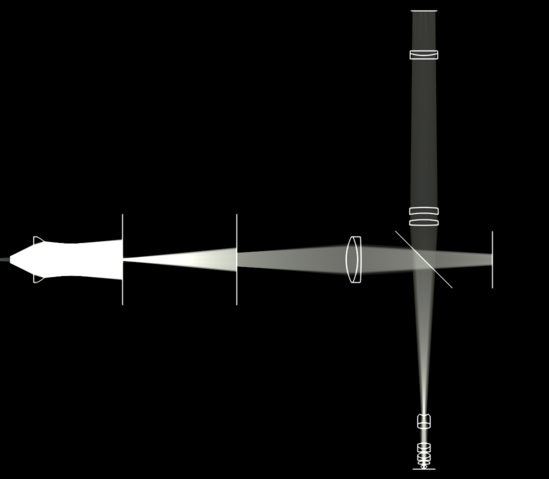
To breathe some life back into this thread: I spent quite some time reconstructing the Microstar IV microscope body and objectives from Reichert/Cambridge patents in order to perform a full spectral optical simulation of the whole system. What follows is a fully virtual reconstruction, based on real lens and glass specs.
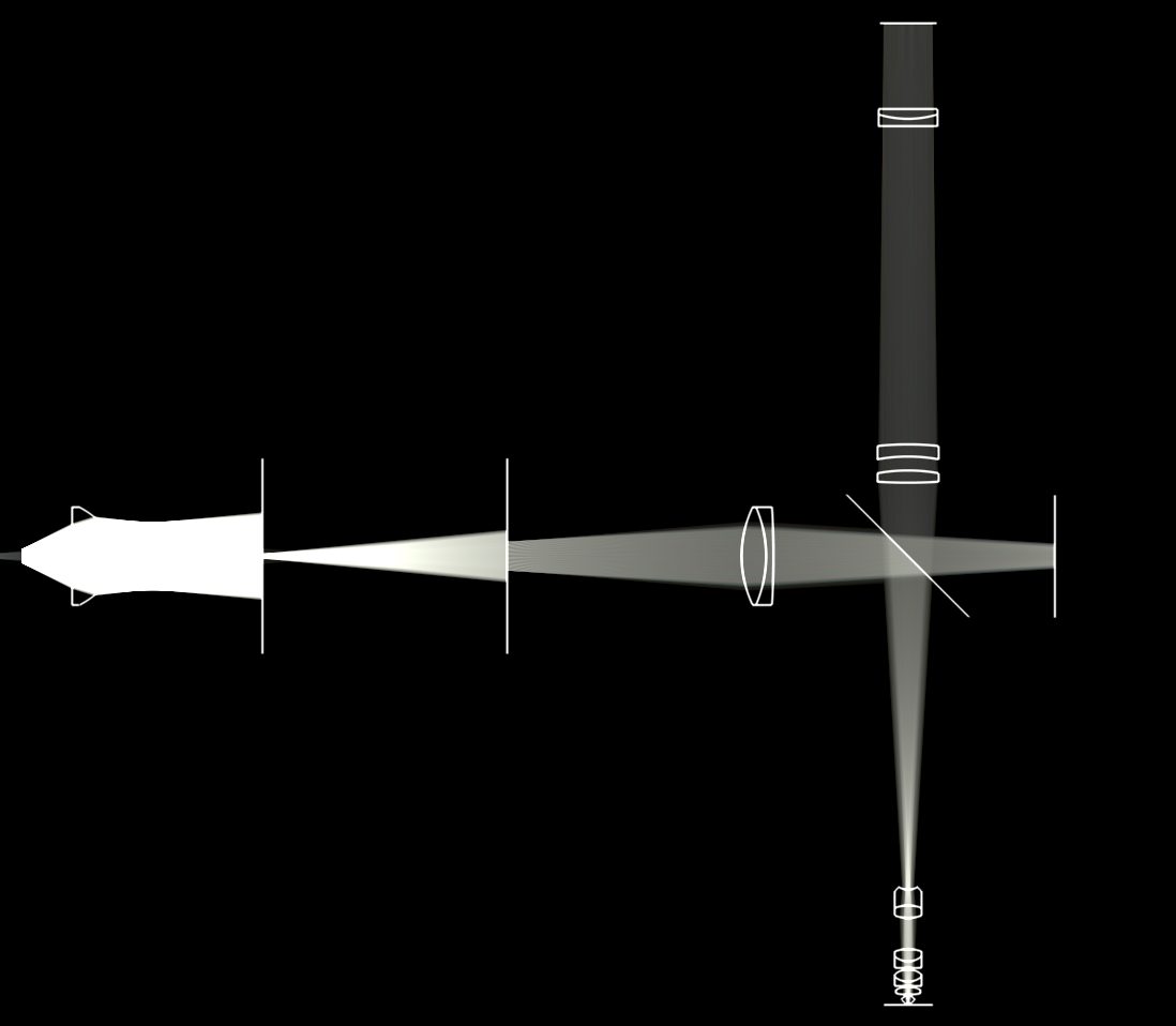
I'm showing a zoomed out image of the entire simulation below (click for full size):
As a basis, I used the
"Microscope body system" (US 4715697A) patent. For the objective, I used the five-component objective from
US Patent 4417787A, which is claimed to be a 50x 0.85NA semi-apochromatic objective.
I determined the focal length of the objective by passing collimated light through it from the back and noting the focal point. Then, I determined the focal length of the tube lens by aiming light from a pinhole emitter through the objective and the tube lens and noting where the light was imaged the sharpest.
Somewhat interestingly, the focal point of both the objective and the tube lens are different than claimed in their respective patents. For the objective, the focal point was 0.0046mm lower than claimed (this seems small, but at 0.85NA it is quite significant). Similarly, the focal point of the tube lens seemed to be a 172mm from the top of the tube lens vs the 193.725 claimed in the patent.
A bigger challenge was the illumination system: Lacking the description of the exact illumination system and condenser used in the Microstar IV, I created a DIY epi-illuminor. It uses an
EdmundOptics aspheric condenser lens as the collimator and a
Thorlabs AC254-100-A Achromatic Doublet as the field lens. Light from a virtual filament is projected at infinity by the condenser, and then refocused at the back focal plane of the objective before passing through a beamsplitter. The use of epi-illumination allows use of the objective itself as the condenser, working around the missing Reichert condenser description. I'm also using two iris diaphragms to control field and aperture of the system, placed at the correct points in the illumination system.
The total system uses a smattering of 12 (!) different types of glass. I spent quite a bit of time trying to track down the original glasses used for lens construction from just the index of refraction and Abbe number specified in the patents in order to retrieve the Sellmeier coefficients. About half I was able to match exactly, the other half I had to find a closest fit (from Schott or Ohara Glass), with an error of a few% in the Abbe number or refractive index.
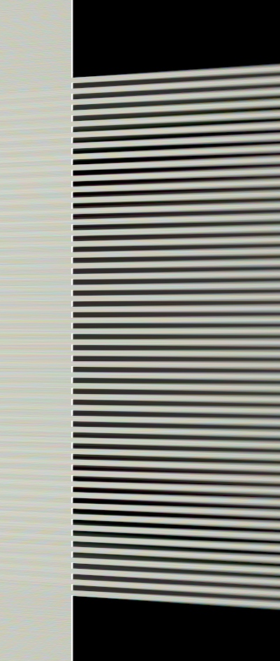
Now on to the experiment: I modified the field diaphragm to project very finely spaced lines onto the objective. I did this by placing finely spaced occluders into the field (shown below).
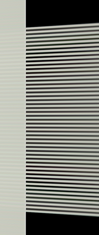
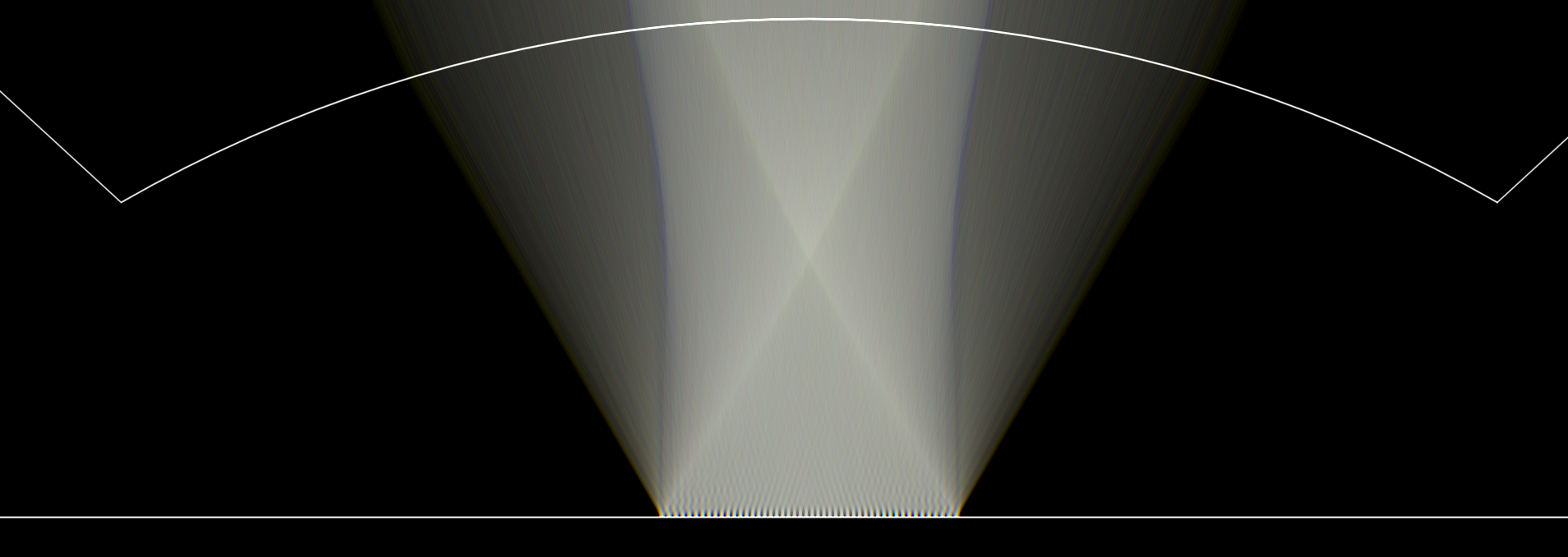
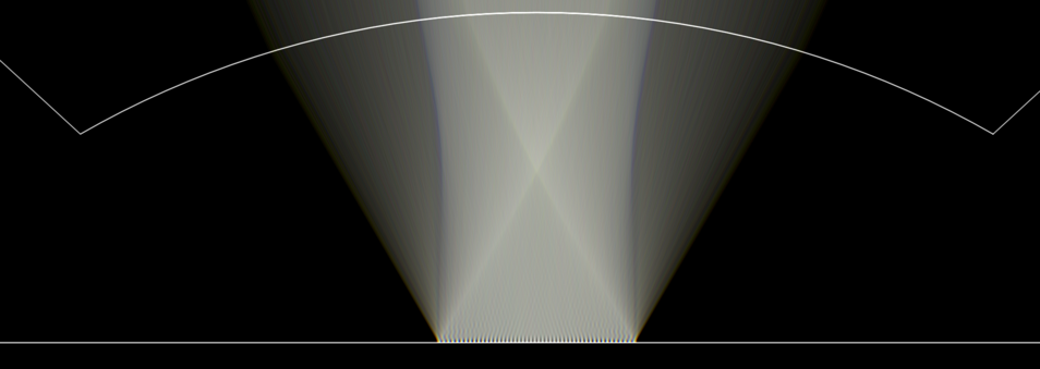
The objective projects these lines cleanly onto the sample plane as we would hope and focuses the reflected light back up at infinity. Below we can see a very zoomed in view of the sample plane, with the bottom-most lens of the objective at the top of the image, and the objective focal plane below it. We can see the finely spaced lines coming into focus and being reflected back (click image for larger version):
The tube lens refocuses the image at the sensor plane, where we can measure it. Below I'm showing the raw image measured by the virtual sensor. We can see the lines mostly in focus, but with significant amount of lateral CA (click image for larger version):

Now the interesting part: I then inserted the color correcting doublet from the patent into the light path between the tube lens and image plane. I'm showing multiple images recorded by the sensor below, that correspond to different distances between the top of the tube lens and the doublet, ranging from 10mm, 50mm, 90mm and 130mm (click images for larger version):


As we can see, the doublet has a significant impact on the amount of CA present in the image. The correcting effect is stronger the closer the doublet is to the tube lens (or, the farther it is from the image plane). Too close and you get reversed CA; too far, and you get barely any correction. The ideal location seems to be somewhere between 50mm and 90mm.
Now, there are obvious caveats in this: This is a simulation following the patent only, but of course we don't know what was actually implemented. Second, I'm using epi-illumination which this objective was likely not designed for. Third, I'm using best-match glasses - we don't know the precise type of glass used in the original system. Fourth, the measured focal points in the virtual system are different from the patent. Is the simulation wrong or the patent? We don't know. Fifth: From the amount of spherical aberrations at the borders it is likely I am imaging a much larger field of view than intended for this objective. The relevant areas are likely the center parts. Sixth, and the most significant one: To get a useful correction, I had to
swap the glass material of the two elements in the doublet. If I use it as specified in the patent, I get CA correction in the wrong direction (i.e. intensifying the CA already present). After swapping the material of the first and second element, the doublet works as intended. A typo in the patent? I do not know.
In any case, I hope this is interesting. Certainly a lot more effort than is reasonable, but it was an interesting endeavor.