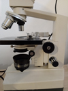
First impressions, built like a tank. To my surprise everything moved freely and nothing was missing. Judging by the accumulation of dust it had been retired to storage uncovered for many years. After a good clean I began checking things over, both the coarse/fine focusing knobs operated smoothly with no sign of vertical stutter or binding. The x/y stage controls moved very freely, too freely, and had long since lost any damping and lubrication. A close examination of the condenser, objectives, and head unit showed no delamination or fungus, only one problem, a cracked leaf spring on the flip-top condenser which hindered secure holding of the top lens against the limit stop when swung in. Even the halogen lamp and control unit worked, and no seized controls on the lamp unit. After more dismantling, cleaning and testing It became obvious the engineering of the unit was top-notch and despite its age and long working life none of the control mechanisms had any slop or displacement.
I managed to find a PDF of the manual, specifications and a Vickers price list. This unit in its current configuration was over five thousand pounds in 1978. It dawned on me I'd landed on my feet with this one.
Plan of action. I want LED illumination but without damaging the halogen unit so it can be reversed if required. The stage has wear marks from usage and needs refinishing and a full clean/re-lube of controls/bearings. The condenser has no filter tray so something will have to be made. The illumination optics needed a little cleaning. Nothing wrong with focus mechanism (sealed behind bellows) don't mess with it. The photo tube needs modifying for use with projection eyepieces and a DSLR.
First up the condenser. This is a dry flip-top aromatic with a max NA of 90, unusually (to me) the iris diaphragm is sandwiched between 2 lenses internally and adjusted by a collar at the base. I made a replacement leaf spring from a 0.3mm feeler gauge (oh the joys of drilling spring steel) and a 3D printed attachment produced for the base of the condenser which has a steel ring embedded within it. This allowed the use of small magnets to hold diy 3D printed filters, held lightly they are quick to change and rotate freely.

The removable turret needed no work and is impressive in both quality and weight. There are 2 holes in it's periphery for each objective which via an internal mechanism allow small lateral adjustments to be made with a small allen key to ensure each objective is concentric.

The original lamp housing could be split into 2 halves after the removal of 3 screws. Using the original I designed a 3D printed replacement which incorporates a heavy heatsink and clamps for a Cree XHP50 5k LED (12v, 19W max), and a sliding shutter for the re-used diffusion glass of the original. Care was taken to ensure the positioning and distance of the LED is identical to the original lamp filament, as is the diffusion filter. Some testing showed the XHP50 was undesirable, uneven phosphorous distribution caused blotchy colour spots visible when focussing the lamp, the four segments of the LED's 5mm die construction also clearly visible. The last photo below shows its replacement (in badly brushed blackout paint), a XHP35 (12v 12W max), this is a single die LED and 3.5mm vs the 5mm of the XHP50. This very closely matches the size of the original halogen filament and exhibits none of the uneven colour distribution or segments of the XHP50. I tried hard to get an XHP35 HI which has no dome lens and designed for use behind secondary optics, but the Coronavirus situation has limited supply severely. I've got one on back-order but may take some time.

Modifying the Photo tube for use with projection eyepieces and a DSLR was fairly simple. One of the existing units of the Vickers photo system incorporated a shutter mechanism and had an original dovetail flange. Rather than use a weak 3D printed dovetail adapter I removed the shutter mechanism guts and made the DSLR adapter to fit inside that. Point of note to experimenters printing microscope adapters, cheaply available M42-DSLR adapter rings are easily glued into a recess and far more durable than 3D printed bayonet mounts. The support arm and base of the photo column have light traps incorporated so it was simple to 3D print 2 intermediate tubes to accommodate the different focal lengths of the two projection eyepieces I use (more on that next).

On the subject of projection eyepieces and the flange step to sensor distance.. I've read various figures stated for Olympus NFK 125 LD eyepieces from 125mm to 150mm (the distance between the step on the eyepiece which rests against the photo tube, and the cameras sensor). My findings are very different. The photo tube base on both my microscopes are par-focal with the main head eyepieces (if you place the LH binocular eyepiece in the photo tube you see the same as through the head eyepieces), in this situation the best flange to sensor distance for my NFK eyepiece is 165mm to be accurately par-focal with the camera. I've tested this extensively. Below are the two projection eyepieces I use, one is an unbranded 2.5x which has a slightly longer par-focal distance of 175mm, hence the need for 2 different length intermediate tubes for the photo column. This unbranded one is a mystery, its performance is very good, if anyone has information on it please post.

Printed a control box which houses a cheap PWM motor controller. I replaced the linear 100k potentiometer with a logarithmic one to give more control at lower illumination levels and added a 32k series resistor which limits the full travel of the pot to 700mA (8.4W @ 12v). This unit operates between 13 and 22kHz along this range. Edit: 31-3-20. After editing a video today I discovered faint strobe lines present, my initial tests of this PWM driver missed them, my apologies. I don't recommend you use this driver for your own projects. since my interest is mainly video I plan on making a flash system using a half mirror as and when I need one.

The stage was the biggest part of the refurb. After fully dismantling the stage and controls they were degreased and cleaned. The bearings and the retainers were thankfully undamaged. The control column had a small amount of corrosion on the friction spring washers which was easily cleaned off. The stage itself was stripped and any pits filled with epoxy, 3 fine grades of wet abrasive paper on a thick glass sheet was used to bring the surface flat, followed by 4 light coats of Simoniz satin black tough paint, how durable this is remains to be seen but so far is working well. Lubrication. The XY stage roller bearings and rack were lubricated lightly with Aeroshell 7 grease, this is a synthetic base grease with low volatility used for aviation instruments, I happen to have some, so why not go OTT