Here is a parts list Not included are two resistors, 1K and 15k, and a 10k potentiometer.
LED substrate:
https://www.mouser.com/ProductDetail/be ... cycode=USD
Cree LED
https://www.mouser.com/ProductDetail/cr ... cycode=USD
LED Driver (0-10v dimmer)
https://www.digikey.com/en/products/det ... 00/2720720
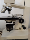
It definitely needs a good heatsink as I cooked one of the LEDs with about 2 hours of use due to not enough thermal contact with the aluminum I had it mounted on. In this revised version, I used a small heatsink to mount the LED to and an aluminum plate I cut to match the mounting bracket of the original light assembly. I chose one of my more beatup stands in case I messed up, but the cosmetics don't affect performance.
Here's the schematic, I'm pretty sure it's accurate.
- led_schematic.jpg (73.75 KiB) Viewed 8370 times
- AO10_led_power_jack.jpg (59.54 KiB) Viewed 8370 times
- AO10_led_mounted_pot.jpg (81.52 KiB) Viewed 8370 times
- AO10_led_wiring.jpg (88.36 KiB) Viewed 8370 times
- AO10_led_knob.jpg (82.6 KiB) Viewed 8370 times